mel
Members
-
Joined
-
Last visited
Never
Everything posted by mel
-
Thanks for your reply.
-
Will the SAB sound when I open the panel box? If so, how would I silence the SAB while I'm testing the keypads?
-
Hi, I self-installed a Euro Mini about a year ago. I have two keypads installed, one upstairs and one downstairs. It's been working fine since I installed it but now its giving me error 485 COMMNS LOST. Neither of the keypads respond. If I open the panel box or the keypad to fault find, the tamper alarm will sound and I have now way of overriding it! 1. Any ideas what would cause this problem (error 485)? Does the keypad or panel have a keypad fuse? If so would a blown fuse cause this error? 2. Without a working keypad, how do I override the tamper alarm? Thanks in advance.
-
Hi James, If you're referring to eolInSeries5, you're absolutely correct. I have scrapped that idea. Too complex. However, in eolInSeries6, if any or all the alarm contacts open, there is only one path. And that path is R1+R2. So, if I chose R1=1.2K and R2=8.2k, the total resistance in that path will be 9.4k. Since my panel is programmed for 4k7 and 4k7, this will give me 9.4k for alarm condition. Exact resistance match! Whilst the alarm contacts are closed, total resistance need to be 4.7k (EOL resistor of 4.7k). That's, R1+(R2 in parallel with Rs) R2=8.2k, Rs = 6.2k, parallel value is 3.53k Therefore, total resistance when alarm contact are closed is 1.2k+3.53k = 4.73k. This is exactly what we need for normal condition. As far as I can see, one can use as many devices in series with this configuration without altering resistor values. This also provides short circuit protection of the alarm lead. Any attempt to short circuit to 0v will effectively make the total resistance of circuit the value of R1, 1.2K, which hopefully is low enough to trigger a tamper condition. There are other resistor combinations that can be used to chive the same results. One other combination I worked out is R1=1.8k, R2=7.5k, Rs=4.7. In this case R1+R2 = 9.3k (hopefully with in tolerance of panel) when alarm contact open. In normal condition, R1+(R2||Rs); R2||Rs = 2.89k, therefore total resistance is 2.89k+1.8k = 4.69k. (hopefully this is also with in panel tolerance) Please do correct me if I have missed anything. I appreciate your response. Mel.
-
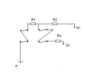
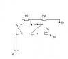
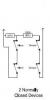
I think this can still be simplified. See attached diagram. With this configuration, one can add as many devices as one requires (within system limitations) in series providing full FSL. If I change the resistor values to better suit the situation, the values become R1 = 1.2k, R2 = 8.2k and Rs = 6.2k When alarm contact become open circuit, we have 1.2+8.2 = 9.4 (alarm condition). Short circuit tampering on alarm wire to 0v, circuit resistance becomes 1.2K - tamper. Can anyone spot a problem with this?
-
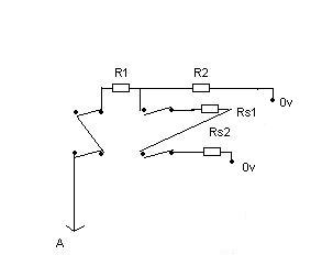
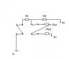
After some more analysis of the circuit I posted, it looks like it is still susceptible to having the alarm lead shorted to 0v without tamper detection, thereby disabling the alarm contacts of the consecutive devices in the chain. So, I have come up with another idea which seem to detect tamper in all cases. Please let me know if I have missed anything. See attached diagram. How it works:- Panel programmed for 4k7 EOL and 4k7 shunt. When in normal condition, the panel must see a 4k7 between A and 0v. I chose 2k7 for R1. Therefore, R2 in parallel with Rs1+Rs2 must = 2k. Also, when any one of the alarm contacts open, R1+R2 must = 9.4k therefore R2 must = 6.7k. Preferred value of 6.8k. 2.7k+6.8K = 9.5k, which should be within panel tolerance (remember also that resistor tolerance would also effect the final value). To calculate the value of resistors in parallel we use 1/(1/R1+1/R2+...1/Rn) Remember that R2 in parallel with Rs1+Rs2 needs to be 2k. Lets call Rs1+Rs2, Rst. So we now have, 1/(1/6.8+1/Rst) = 2 If we rearrange that, we have 1/Rst = 0.5 - 1/6.8 1/Rst = 0.353 therefore Rst = 2.83 i.e Rs1+Rs2 = 2.83. therefore Rs1=Rs2= 1.415k. Preferred value of 1.5k. Now, if one attempts to short the alarm lead to 0v, this would cause the circuit to change its over all resistance. In effect, it will become R1 + (R2 in Parrnell with Rs1), 1/(1/6.8+1/1.5) = 1.23k 2.7+1.23 = 3.9K. This is less than 4.7k and should cause a tamper condition. Mel.
-
Hi James, Thanks for the diagram. I don't understand what the +ve and -ve terminals are. You refer to those terminal as 'feed'. Could you explain what they are please. Thanks. Mel.
-
James, I would be most grateful if you could post a diagram for me. Regards, Mel.
-
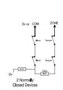
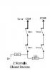
I had emailed castle care-tech several days ago regarding this issue. They replied with the following description:- "The first N on the first PIR to panel Zone, wire the 4K7 resistor across the N/C and just a link between C and the first T. The second T goes to N on the second PIR and so on. The final PIR has the 2K2 resistor in place of the link and the second T to the panel Common." I drew a diagram to that description which castle confirmed as being correct. Please see below. To my amateur eyes, it doesn't look right. Anyone walking in front of PIR2 or PIR3 will cause a tamper condition, surely?
-
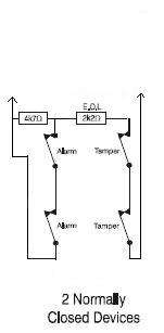
Yes. You're absolutely correct. I didn't spot that. If my understanding is correct, please correct me if I'm wrong, on some panels the 'COM' terminal are the same as 0v terminal. Are you able to confirm if that is the case with the mini euro please? Assuming for the moment that that is the case, if the circuit was rearrange as shown, I think it satisfies all conditions.
-
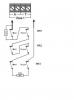
I have rearranged the circuit slightly. I think this is more secure, although it does mean using four wires.
-
Thanks for the diagram. I knew I had to get the alarm switches, wired in series, in parallel with 4k7. I just couldn't visualise it. From the diagram, it looks like I will need to use three wires to achieve this. Assuming I placed the 4k7 in the last device and using a spare core form the cabling to connect the other end of the resistor to one of the alarm contacts on the first device. What would happen if that return wire was severed for what ever reason? Ordinarily, I would expect the system to sound a tamper or alarm. However, because all the alarm switches are closed, the system does not detect either of those conditions. Would that be correct?
-
Hi, I have a Castle care-tech euro mini and need to add another PIR to a FSL zone which already has a PIR. i.e. I need to wire two PIR's in series. Unfortunately the manual does not give any details how to do this and I have not found any helpful information on the net either. I would be most grateful if someone can point me in the right direction to achieve this. Thanks in advance. Mel.
-
Ok. I managed to find out for my self by downloading the installation manual from the manufacturers web site. The helpful chap I spoke to let me have the username and password for the download area. For those who might also be interested:- 1. EOL and FSL are the same thing. 2. EOL resistor 2K2 and alarm contact shunt 4K7 or use 4K7 for both EOL and shunt. 3. This unit can take a 7AH or a 17AH.
-
Hi, I would be most grateful if someone could answer the following question regarding this panel as I can't seem to get hold of the installation manual for it. 1. Product description for the Euro Mini says that this panel has 10 EoL zones. Does that mean that it is FSL capable? 2. If so what are the resistor values? 3. I'm assuming that I would require a 12v 7AH backup battery for this panel. Would that be correct? Thanks in advance.
-
Thanks for a very prompt response. If I understood that thread correctly, I think THAT was the whole problem. An engineer on that same thread experimented with a brand new panel and found that it was not possible to disable engineers access. Is there an advantage of wiring FSL over CC, apart from the obvious of using less wires?
-
(Apologies to those who have seen this post already. I realised that I had posed it on the wrong board.) Hi, I'm looking to purchase an alarm system. Currently my short list of panels are:- Texecom VERITAS EXCEL ADE Accenta Mini Gen4 Scantronic 9651 I was hedging on towards the 9651 until I read about a 'engineer code guard feature' that doesn't seem to work. Here is the link where I stumbled across this issue. Sorry it's a bit long, but towards the end of the page they say that it is a software problem although not openly admitted by the manufacturer. http://www.thesecurityinstaller.co.uk/community/lofiversion/index.php?t24279-0.html I suppose one can always change the default engineers code to avoid that situation. Are you able to confirm that the units supplied by your selves does not have this problem? Are there any other panels you can recommend in the same price range as those listed above?